WAN Architecture
Metro Ethernet Physical Design and it’s Topology:
Metro Ethernet (MetroE) includes a variety of WAN services with some common features. Each MetroE service uses Ethernet physical links to connect the customer’s device to the service provider’s device.
Although the main concept makes a Metro Ethernet service act like a big LAN switch, there are many options, and you should understand the basics of each. Additionally, many customers connect to a Metro Ethernet service with either routers or Layer 3 switches, which brings up some Layer 3 issues with IP addressing and routing protocols.

From the SP perspective, the SP needs to build a network to create the Metro Ethernet service. To keep costs lower the SP puts a device (typically an Ethernet switch) physically near to as many customer sites as possible, in an SP facility called a point of presence (PoP). Those SP switches need to be near enough to many customer locations so that some Ethernet standard supports the distance from the SP’s PoP to each customer site. You can observe the same in the image below.

Working through the details in the figure, the physical link between the customer and the SP is called an access link or, when using Ethernet specifically, an Ethernet access link. Everything that happens on that link falls within the definition of the user network interface, or UNI. Breaking down the term UNI, the word network refers to the SP’s network, while the SP’s customer (the enterprise) is known as the user of the network.
The SP’s network remains hidden to a great extent. The SP promises to deliver Ethernet frames across the WAN. To do that, the access links connect to an Ethernet switch. As you can imagine, the switch will look at the Ethernet header’s MAC address fields and at 802.1Q trunking headers for VLAN tags, but the details inside the network remain hidden.
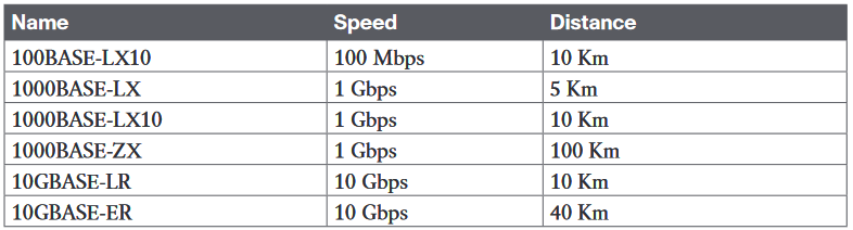
The table below represents the some of the standards that you are expected to see over an Ethernet Access Link
Ethernet WAN Services and Topologies:
MEF (www.mef.net) defines the standards for Metro Ethernet, including the specifications for different kinds of MetroE services. Table below lists three service types described in this chapter and their topologies. The next few pages after the table go into more depth about each.

Ethernet Line Service (Point-to-Point):

As with all MetroE services, the promise made by the service is to deliver Ethernet frames across the service, as if the two customer routers had a rather long crossover cable connected between them. We can deduce the following from the figure above.
■ The routers would use physical Ethernet interfaces.
■ The routers would configure IP addresses in the same subnet as each other.
■ Their routing protocols would become neighbors and exchange routes.
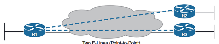
The MetroE specifications define the concept of an Ethernet Virtual Connection, or EVC, to define which user (customer) devices can communicate with which. By definition, an E-Line service (as shown in Figure) creates a point-to-point EVC, meaning that the service allows two endpoints to communicate.
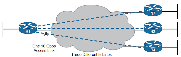
For example, think of a common enterprise WAN topology with a central site and 100 remote sites. As shown so far, with an E-Line service, the central site router would need 100 physical Ethernet interfaces to connect to those 100 remote sites. That could be expensive. As an alternative, the enterprise could use the design partially shown in Figure above (just three remote sites shown). In this case:
■ The central site router uses a single 10-Gbps access link.
■ The central site connects to 100 E-Lines (only three shown).
■ All the E-Lines send and receive frames over the same access link.
designs like the Figure shown above, with multiple E-Line services on a single access link, use 802.1Q trunking, with a different VLAN ID for each E-Line service. As a result, the router configuration can use a typical router configuration with trunking and subinterfaces.
Ethernet LAN Service(Full Mesh):
In fact, allowing all devices to send directly to every other device sounds a lot like an Ethernet LAN, so the MetroE service is called an Ethernet LAN service, or E-LAN.
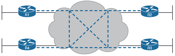
Figure above shows a representation of a single E-LAN EVC. In this case, the one EVC connects to four customer sites, creating one E-LAN. Routers R1, R2, R3, and R4 can all send frames directly to each other. They would also all be in the same Layer 3 subnet on the WAN
Ethernet Tree Service (hub and spoke):
The Ethernet Tree service (E-Tree) creates a WAN topology in which the central site device can send Ethernet frames directly to each remote (leaf) site, but the remote (leaf) sites can send only to the central site. Figure 14–6 shows the topology, again with a single EVC. In this case, router R1 is the root site, and can send to all three remote sites. Routers R2, R3, and R4 can send only to R1
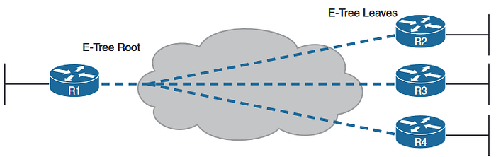
With an E-Tree, the central site serves as the root of a tree and each remote site as one of the leaves. The topology goes by many names: partial mesh, hub and spoke, and point-to-multipoint. Regardless of the term you use, an E-Tree service creates a service that works well for designs with a central site plus many remote sites.
Layer 3 Design Using Metro Ethernet:
we have already covered topics on different types of WAN now we will discuss the same topologies with routers as WAN edge devices.
Layer 3 Design Elan Service:
Let us consider a following example and let us see how packets will be routed through it.
Focusing on the E-Lines and ignoring the access links for the most part, think of each E-Line as a subnet. Each router needs an IP address in each subnet, and the subnets need to be unique. All the addresses come from the enterprise’s IP address space.
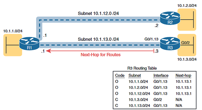
look at R3’s route for subnet 10.1.2.0/24, which supports the fact that R3 cannot send packets directly to R2 with the current WAN design. R3 does not have an E-Line that allows R3 to send frames directly to R2. R3 will not become routing protocol neighbors with R2 either. So, R3 will learn its route for subnet 10.1.2.0/24 from R1, with R1’s 10.1.13.1 address as the next-hop address. As a result, when forwarding packets, R3 will forward packets to R1, which will then forward them over the other E-Line to R2
Layer 3 Design with E-LAN Service:
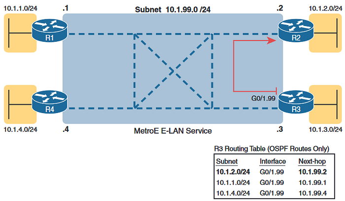
Look at R3’s routing table in the figure, the route from R3 to R2’s LAN subnet (10.1.2.0/24). In this case, R3’s next-hop address is the WAN address on R2 (10.1.99.2), and R3 will send packets (encapsulated in Ethernet frames) directly to R2. Note also that the other two routes in the routing table list the next-hop addresses of R1 (10.1.99.1) and R4 (10.1.99.4).
The details in this first section of the chapter should provide plenty of perspective on how enterprise routers use Ethernet WANs for connectivity. However, if you want a little more detail, the section titled “Ethernet Virtual Circuit Bandwidth Profiles” in Appendix D,“Topics from Previous Editions,” discusses the logic behind how Ethernet WANs use physical links at one speed while supporting services that run at a variety of slower speeds.
Reference:
https://www.amazon.in/CCNA-200-301-Official-Cert-Guide/dp/9353946174